Rocket Nosecone Ejection System
 Rocket Nosecone Ejection System - Mazzo.me
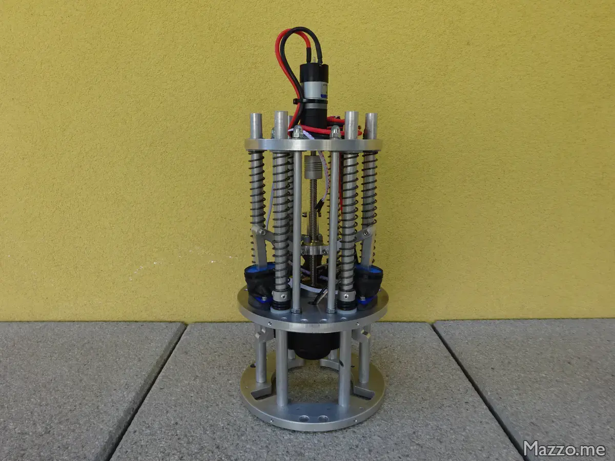
I designed and implemented this system for Skyward Experimental Rocketry. It is used to detach the rocket nosecone and expel the parachutes.
The system works thanks to springs that push the nosecone away from the fuselage and to an electric motor that moves the arms that hold the ogive to the fuselage before ejection.
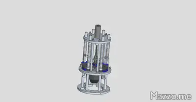
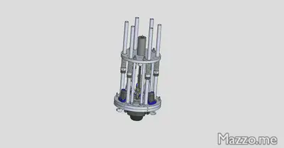
I designed the entire system with the SolidWorks CAD:
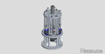
With the two configurations before and after ejection:
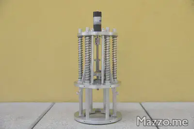
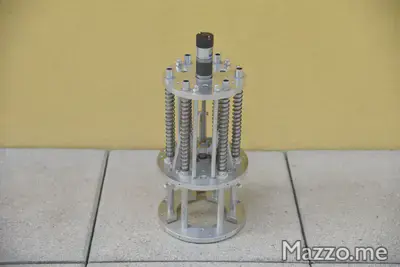
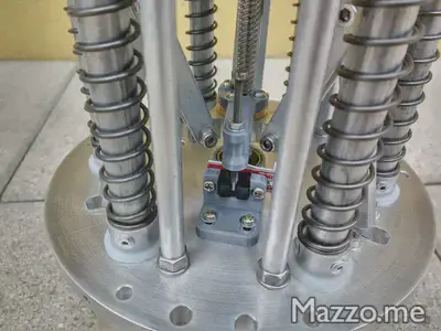
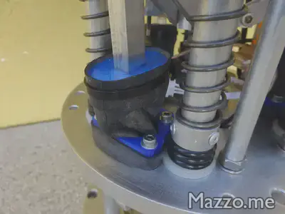
During the realization various modifications and additions were necessary compared to the initial configuration:
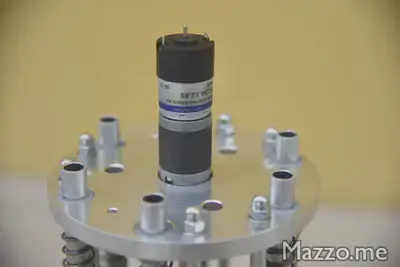
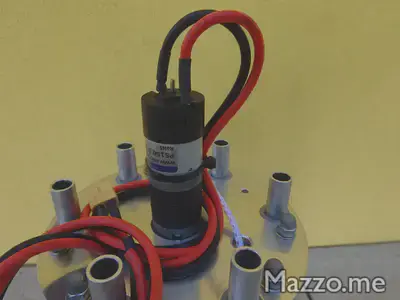
The movement of the arms is done by a 12 V DC motor:
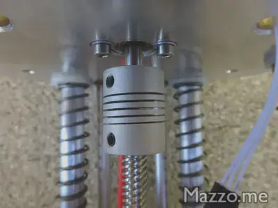
The screw is fixed to the motor with a flexible coupling:
The central part that is moved by the screw was made with my MPCNC:
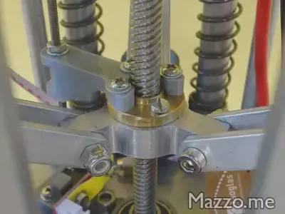
As well as the connecting rods that join this part to the arms:
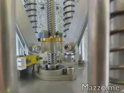
The screw turns on ball bearings:
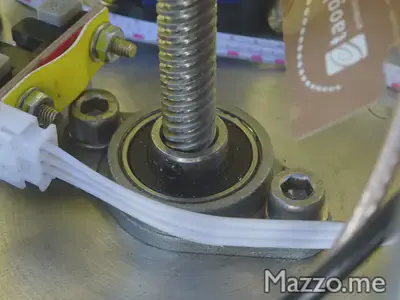
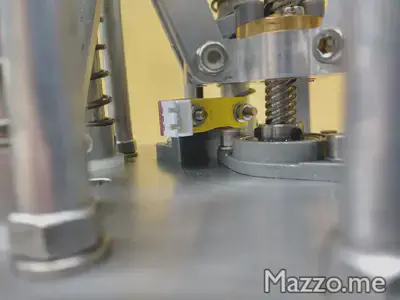
Connectors accessible from the outside allow the motor to be powered if necessary:
To close the system there is an optical limit switch:
Even the moving arms were made with my MPCNC:
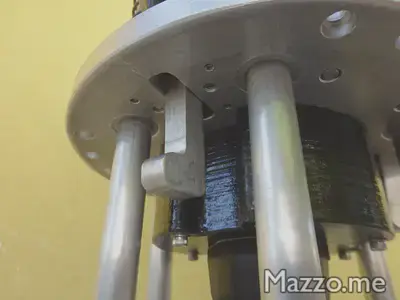
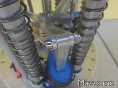
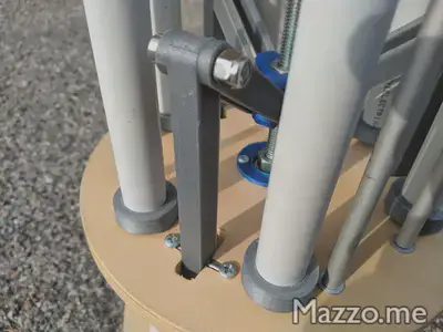
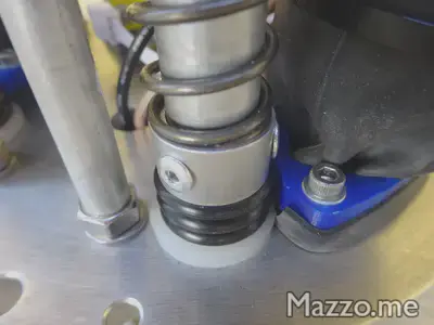
The arms are fixed to the base with a pin that allows the rotation:
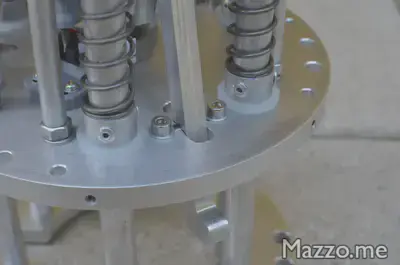
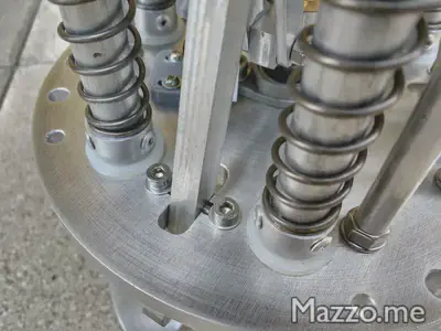
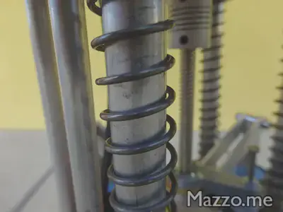
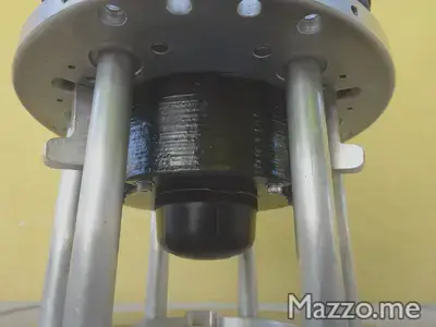
Once dropped the ogive is pushed by six springs:
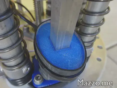
An addition I made after the initial design was to make the system waterproof.
For the movement of the arms I made a coverage with an inner tube and supports printed with my 3D Printer :
There is an antenna for GPS and telemetry:
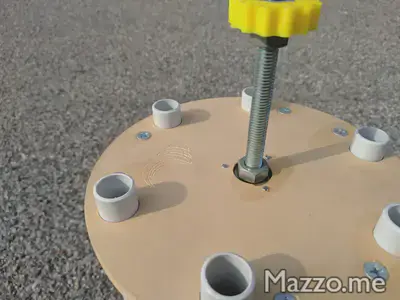
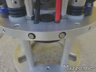
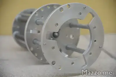
On the fuselage support base there are three screws not arranged symmetrically to have only one possible mounting position:
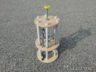
Before creating the final system I also made a model in plywood and plastic: